
VIBRANCE: GRAPHIC VISUALIZER
For my final project, I created a graphic visualizer, including a control board and a program to create the visuals. The concept for this project came to me while I was at a concert (I get all my best ideas at concerts), because I really love the concert visuals used by a lot of electronic artists, I find them to be very inspiring. I’ve been learning about music synthesis in another class, and so I thought I would try to make a visual “synthesizer” with a similar concept.
After further developing the concept, I decided I wanted to create something that could make beautiful visuals with very little effort, knowledge, or even artistic intent. I wanted this object to be something that allows people to relax and create with ease. As an added benefit, I thought it could be a good way to break through artist’s block, or even inspire creative ideas.
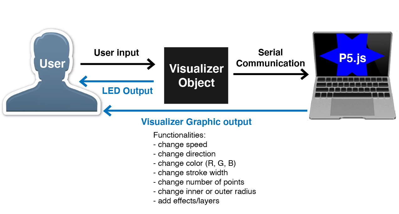
The physical object I created is a control box (“Vibrance”) that uses Arduino to serially communicate with a computer to control a program written with P5.js that would create the visuals. I used both analog and digital sensors, and then used the values from those sensors to control various parameters in the P5.js code. I used potentiometers, switches, and a lot of soldering to create the circuit, which I enclosed in an acrylic box and painted black. The process of how I made the control box is detailed below. The code for the visuals is essentially a star shape that is rotating and constantly updating and redrawing as its given new values from the controls. I had multiple parameters run by sensors, including speed, direction, color, stroke, number of points and size. I also decided to add the ability to create two extra layers to create even more effects. When the layers are activated, a light on the control box turns on to let the user know. Then, the user is able to edit parameters for the topmost layer with the controls. By just adding extra layers, the user can create so many more effects that is seems to become an endless combination. The layers function was the biggest challenge on the code side, but it makes a big difference and was definitely worth it.
Of all the projects I have made so far in my undergraduate career, this one is what I am most proud of. It combines three things I’m passionate about: creativity, visuals, and web coding, plus it’s just a really fun project to play with. I feel that this work really embodies the direction I want to follow in life and my artistic career, and I’m very proud of it. I also completed it by myself, in roughly a month, which wasn’t easy. This project definitely pushed my abilities, and I’ve learned a lot from making it. I would also hope to expand upon this project in the future (Vibrance 2.0), for another Atlas class of even as a personal project.
THE PROCESS
Materials used: Arduino Uno, USB cable, 4 10kΩ potentiometers, 2 10kΩ slide potentiometers, knob and slide covers, 1 two-way toggle switch, 4 toggle switches, 2 blue LEDs, multicolor solid core wire, protoboard, 22kΩ and 100Ω resistors, thin acrylic, black spray paint, e6000, hot glue, electrical tape.
Equipment used: Laser cutter, soldering irons, wire cutters and strippers, hot glue gun.
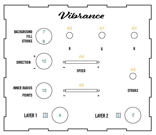
The concept for user interaction is designed as seen below.

After I ordered my initial set of parts, I created a prototype circuit on a breadboard so that I could start preliminary code with serial values from Arduino. I didn't end up using the push buttons, because I realized that toggle switches work much better than momentary ones for the code I was writing, so I changed those inputs to switches.
I also started sketching potential layouts for my board, and figuring out what functions i would assign to each sensor.
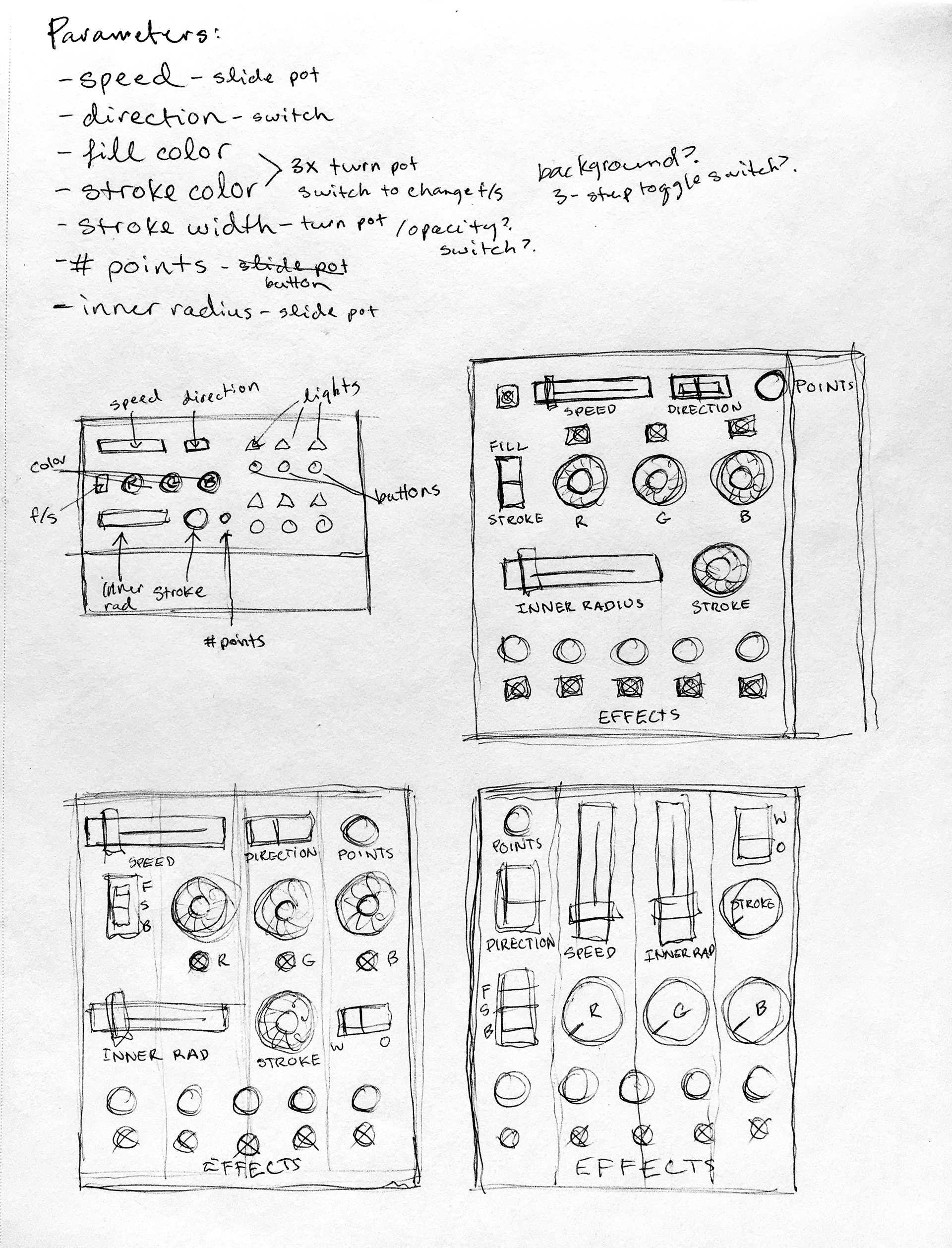
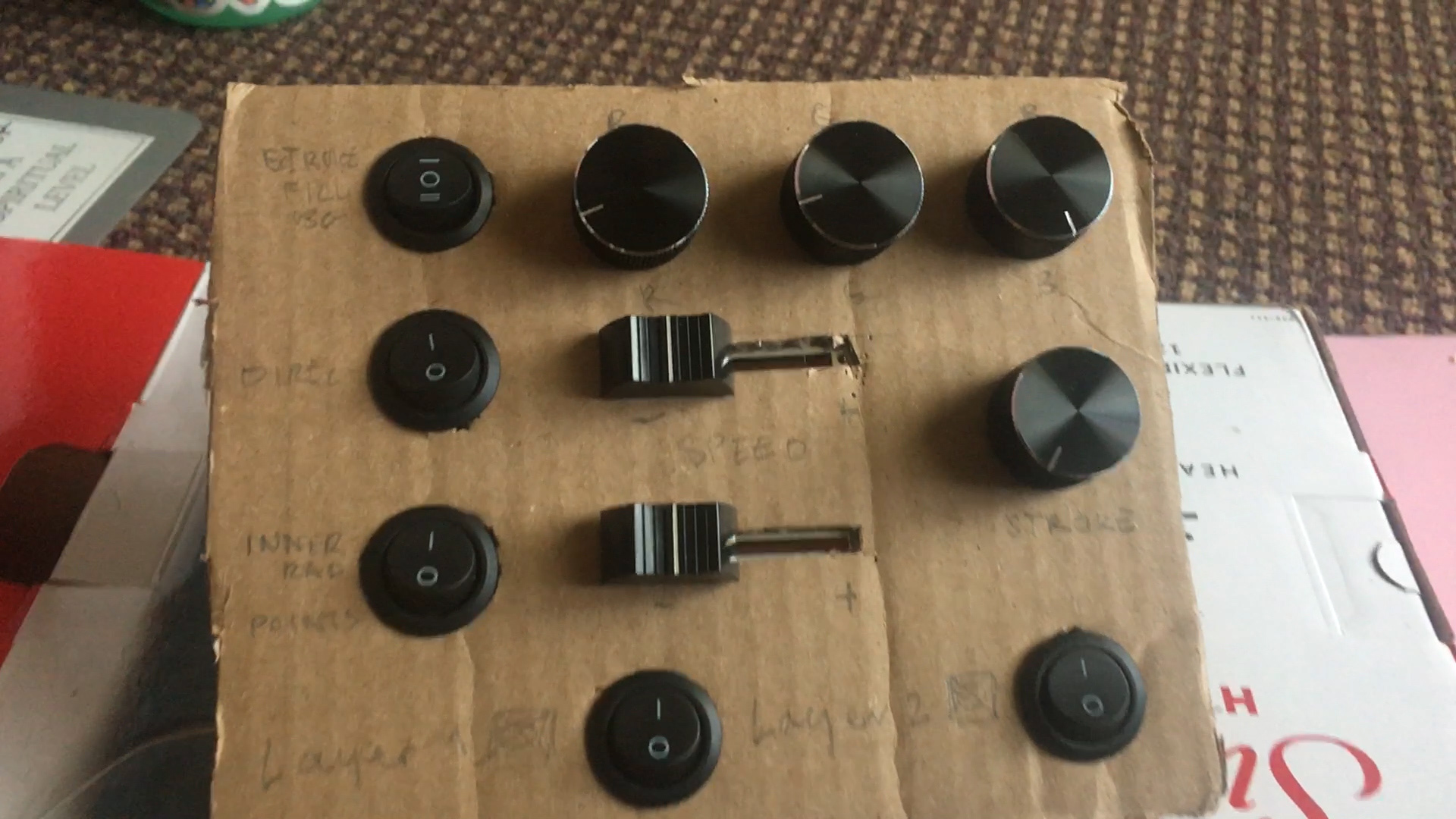
To figure out which layout of my board would be best, I made a prototype from cardboard. I tried plugging these components in to make sure I would be able to once I had the competed enclosure. This also helped me get a physical feel for the layout of each component, rather than just designing it as a 2-D sketch.


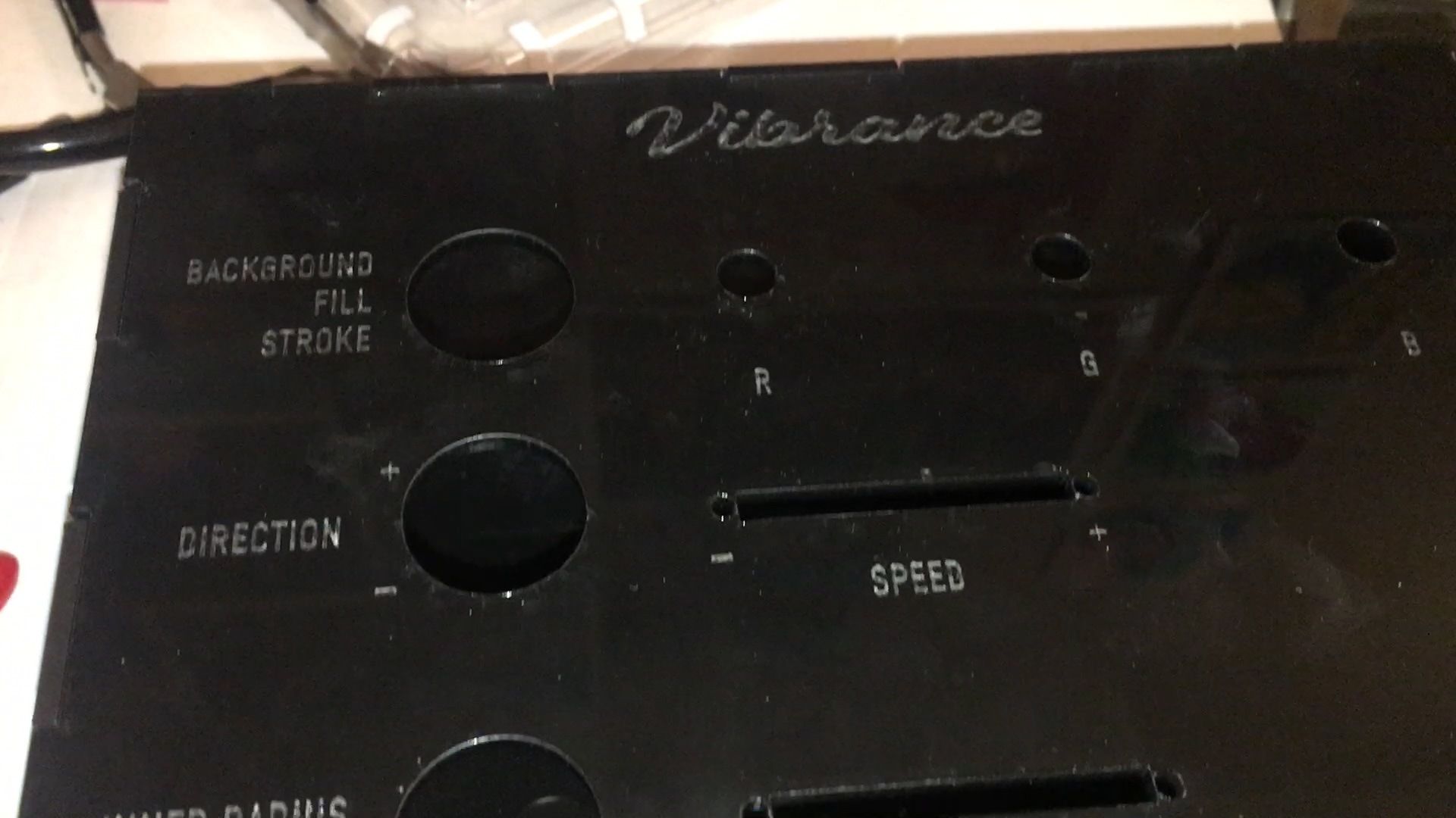
I liked the layout of my cardboard prototype, so I designed my laser cut pattern with the same layout. I used Makercase for the box template, and then created my top layout with illustrator. I used thin acrylic to create the enclosure, and spray painted it black after cutting.

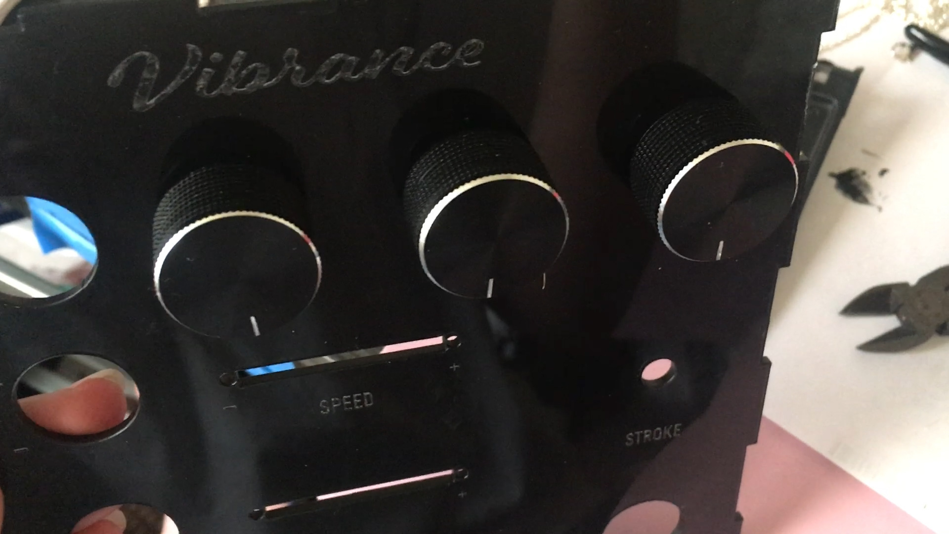
Once the paint dried, I was able to begin attaching parts to the acrylic. I also bought knob covers for all my potentiometers, and it significantly improved the overall look and feel.
I began soldering my power and ground wires for each sensor or switch as I added them to the acrylic top piece.
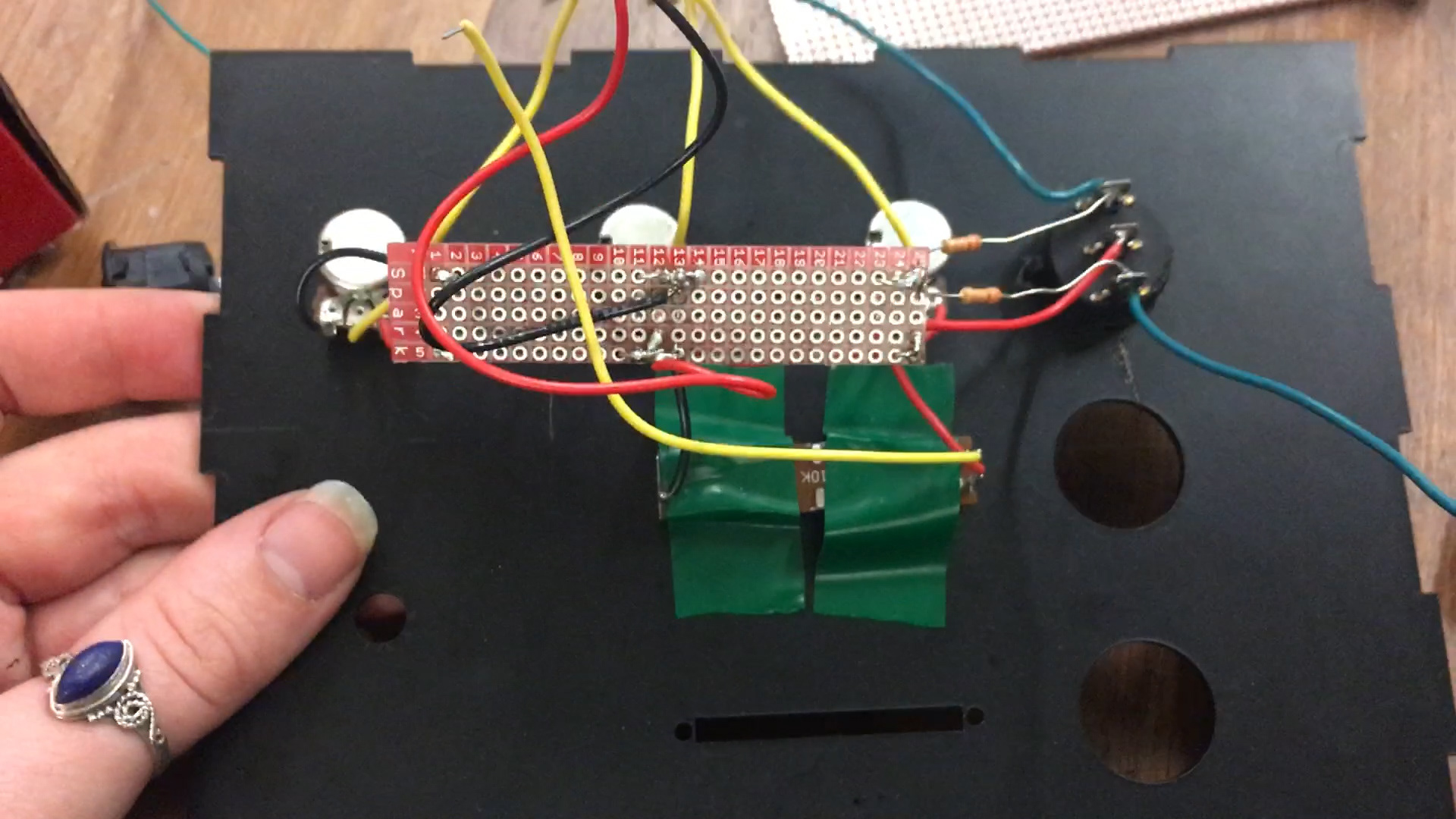
Eventually, I had everything attached and connected to the board. I then has to plug each component in, which was still quite a challenge even though I had tried to deign my layout to help. Luckily, I color-coded my wires to make it easier for myself. (Red: power, Black: ground, Yellow: analog signals, Green: digital signals, Blue: LEDs)
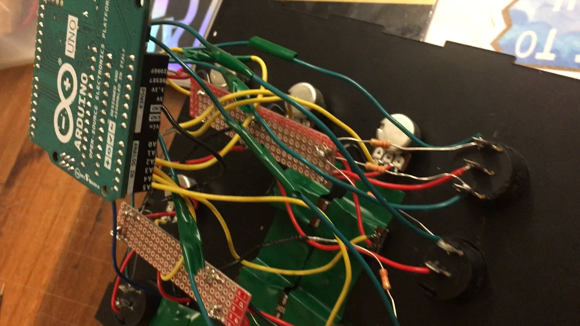
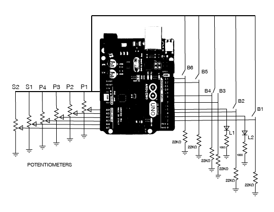
The final circuit and sensor layout was assembled as shown.
I also glued the bottom of the enclosure together with E6000 and gave it another coat of spray paint.

After the glue dried, I was able to put the circuit inside the enclosure and make some final adjustments.
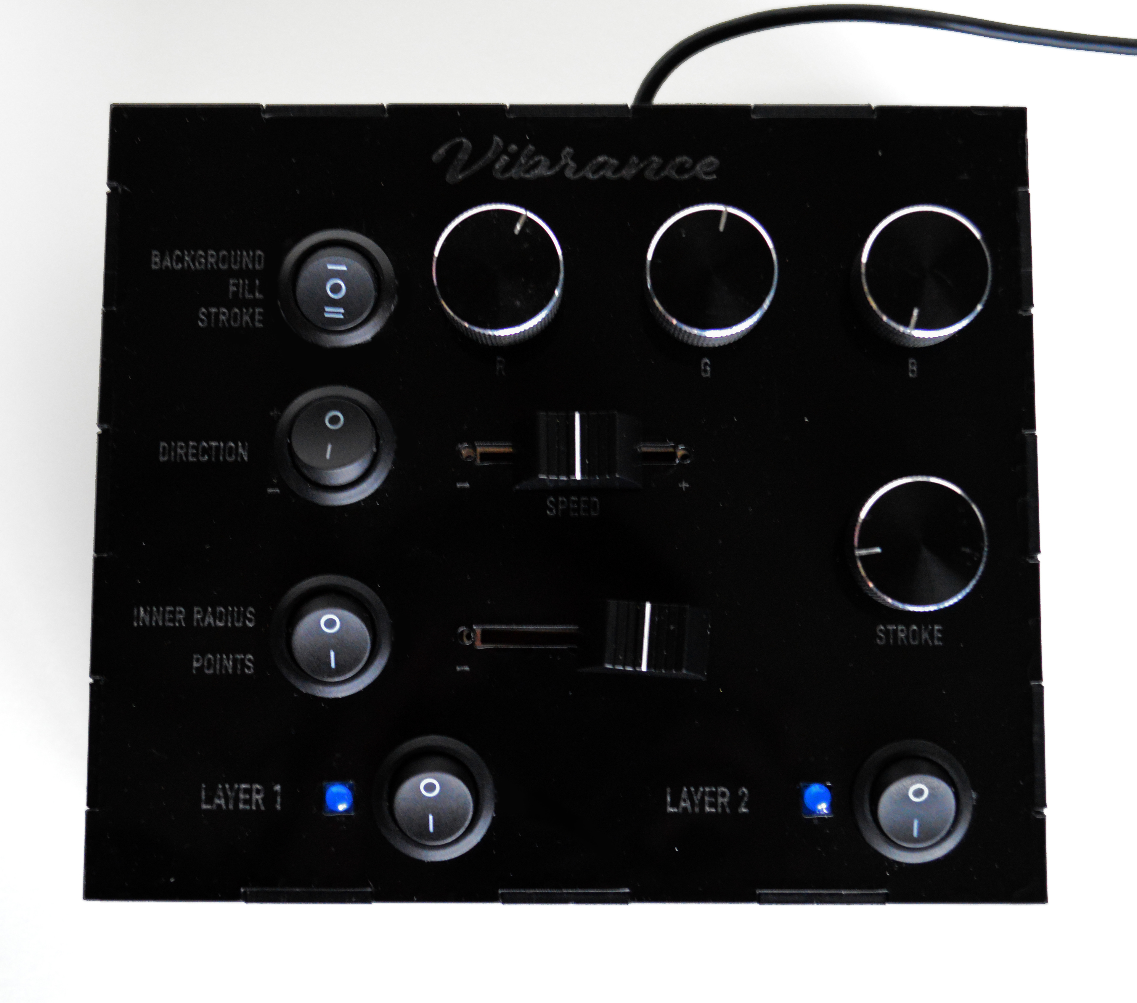
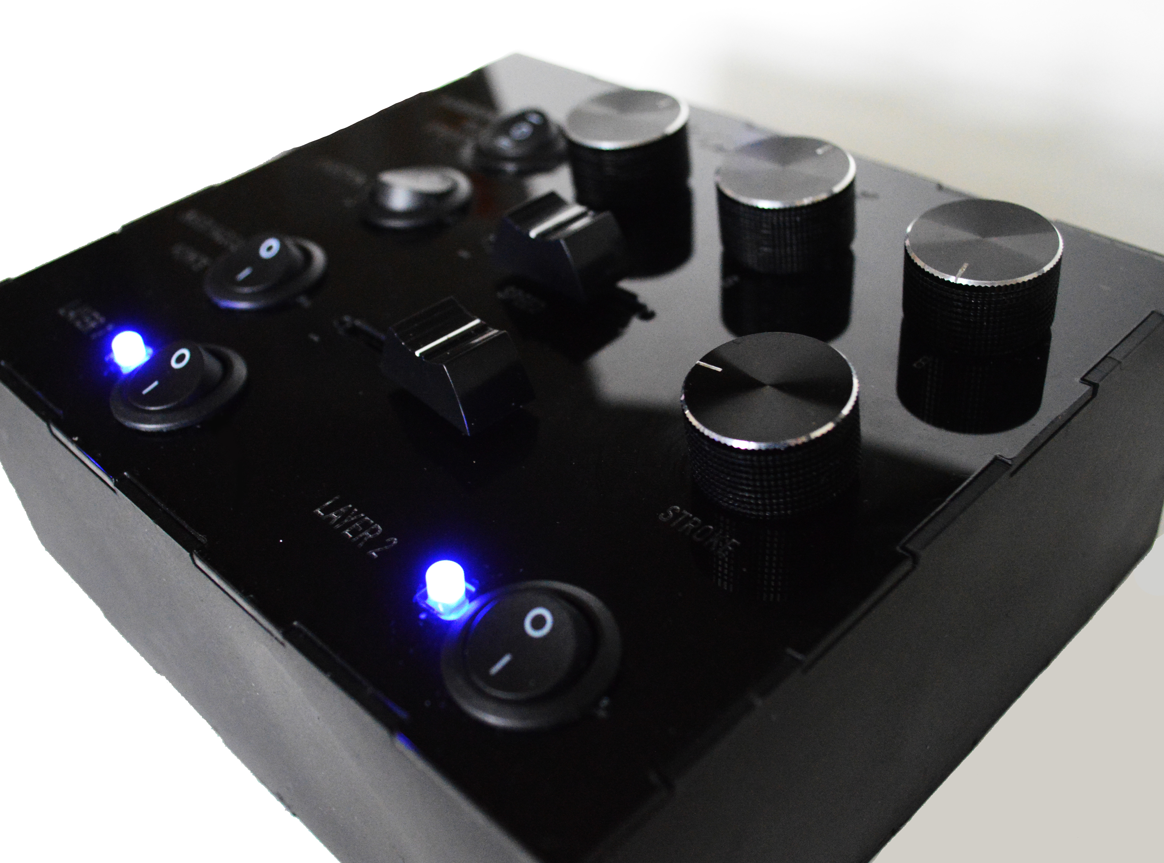
THE FINAL PRODUCT
I created a demo video to show a bit more of the process, and to show off the final object in its full form.
if the video is not working, it's because I used a background song and the video was hidden. There is a muted version available, click here.
CODE
The code for my Arduino as well as the P5.js code for the visuals is linked below.